
Signal Chain Fundamentals #29: Digital Interfaces—A Comparison of Single-Ended and Differential Interfaces

Signal Chain Fundamentals #29: Digital Interfaces—A Comparison of Single-Ended and Differential Interfaces
This "Signal Chain Fundamentals" series introduces you to the digital interfaces necessary for transmitting digital conversion results from an analog-to-digital converter (ADC) to a system controller and for transmitting any digital configuration data from the controller to a digital-to-analog converter (DAC). The two main signal transmission schemes used are single-ended and differential signal transmission.
Single-ended data transmission uses only one signal line, whose potential is considered ground. While the signal line provides a positive path for the signal current, the ground line provides a return path. Figure 1 shows the basic schematic of a single-ended transmission path.

Figure 1 Single-Ended Transmission Path
The main advantages of single-ended interfaces can be summarized as simplicity and lower implementation cost. However, they are highly susceptible to noise pickup because noise introduced into the signal or ground path is directly added to the receiver input, causing spurious receiver triggering. Another problem is crosstalk, especially at higher frequencies, which arises from capacitive and inductive coupling between adjacent signals and control lines. Ultimately, due to the physical difference between the signal traces and the ground plane, the transverse electromagnetic waves (TEM) generated in a single-ended system radiate into the circuit environment, becoming a significant source of electromagnetic interference (EMI) for neighboring circuits.
Differential signal transmission uses a signal pair consisting of two conductors: one for forward current and the other for return current. Each signal conductor has a common-mode voltage VCM, which is superimposed by 50% of the differential driver output VOD, but with opposite polarities (see Figure 2).
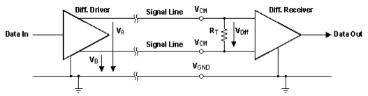
Figure 2 Differential Transmission Path
When the conductors of the differential pair are close to each other, the external noise introduced into the two conductors through electrical coupling manifests uniformly as common-mode noise at the receiver input. Receivers with differential inputs are only affected by the signal difference, but not by the common-mode signal. Therefore, the receiver not only suppresses common-mode noise but also maintains signal integrity.
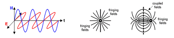
Figure 3. TEM waves radiated from a large scattered magnetic field around a single conductor and a small scattered magnetic field outside the tightly coupled conductor loop by a differential signal line.
Tight electronic coupling has another advantage. Equal but opposite currents in two conductors create some canceling magnetic fields. The TEM waves from both conductors, now having their magnetic fields removed, cannot radiate into the environment. Only a very small electric field at the outer edge of the conductor loop can radiate, resulting in minimal EMI.
Applications
When used close to a system controller, single-ended interfaces allow relatively high frequencies (up to 70 MHz). Differential interfaces offer extremely high noise immunity, significantly reducing EMI, thus enabling data transmission at frequencies up to 500 MHz and even higher.
The most commonly used data converter interfaces are the Internal Integrated Circuit Bus (I2C), the Serial Peripheral Interface Bus (SPI), and the Low Voltage Differential Signaling Interface (LVDS).
This "Signal Chain Fundamentals" series introduces you to the digital interfaces necessary for transmitting digital conversion results from an analog-to-digital converter (ADC) to a system controller and for transmitting any digital configuration data from the controller to a digital-to-analog converter (DAC). The two main signal transmission schemes used are single-ended and differential signal transmission.
Single-ended data transmission uses only one signal line, whose potential is considered ground. While the signal line provides a positive path for the signal current, the ground line provides a return path. Figure 1 shows the basic schematic of a single-ended transmission path.
Figure 1 Single-Ended Transmission Path
The main advantages of single-ended interfaces can be summarized as simplicity and lower implementation cost. However, they are highly susceptible to noise pickup because noise introduced into the signal or ground path is directly added to the receiver input, causing spurious receiver triggering. Another problem is crosstalk, especially at higher frequencies, which arises from capacitive and inductive coupling between adjacent signals and control lines. Ultimately, due to the physical difference between the signal traces and the ground plane, the transverse electromagnetic waves (TEM) generated in a single-ended system radiate into the circuit environment, becoming a significant source of electromagnetic interference (EMI) for neighboring circuits.
Differential signal transmission uses a signal pair consisting of two conductors: one for forward current and the other for return current. Each signal conductor has a common-mode voltage VCM, which is superimposed by 50% of the differential driver output VOD, but with opposite polarities (see Figure 2).
Figure 2 Differential Transmission Path
When the conductors of the differential pair are close to each other, the external noise introduced into the two conductors through electrical coupling manifests uniformly as common-mode noise at the receiver input. Receivers with differential inputs are only affected by the signal difference, but not by the common-mode signal. Therefore, the receiver not only suppresses common-mode noise but also maintains signal integrity.
Figure 3. TEM waves radiated from a large scattered magnetic field around a single conductor and a small scattered magnetic field outside the tightly coupled conductor loop by a differential signal line.
Tight electronic coupling has another advantage. Equal but opposite currents in two conductors create some canceling magnetic fields. The TEM waves from both conductors, now having their magnetic fields removed, cannot radiate into the environment. Only a very small electric field at the outer edge of the conductor loop can radiate, resulting in minimal EMI.
Applications
When used close to a system controller, single-ended interfaces allow relatively high frequencies (up to 70 MHz). Differential interfaces offer extremely high noise immunity, significantly reducing EMI, thus enabling data transmission at frequencies up to 500 MHz and even higher.
The most commonly used data converter interfaces are the Internal Integrated Circuit Bus (I2C), the Serial Peripheral Interface Bus (SPI), and the Low Voltage Differential Signaling Interface (LVDS).
Dec 24,2025