
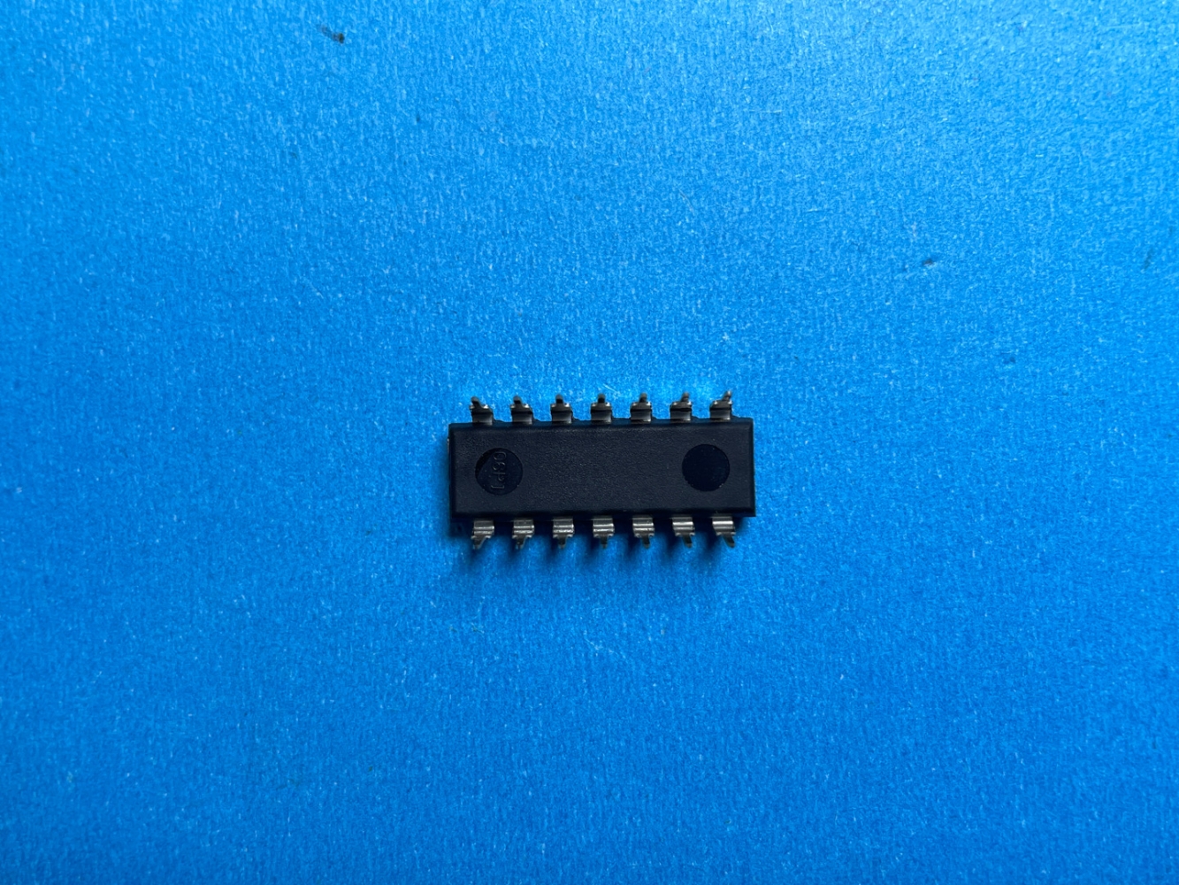
Details
BUY SN74LS90N https://www.utsource.net/itm/p/12597892.html
| Parameter | Description | Min | Typical | Max | Unit |
|---|---|---|---|---|---|
| Supply Voltage (VCC) | Operating supply voltage | 4.75 | - | 5.25 | V |
| Input Voltage (VIH) | High-level input voltage | 2.0 | - | - | V |
| Input Voltage (VIL) | Low-level input voltage | - | - | 0.8 | V |
| Output Voltage (VOH) | High-level output voltage | 2.4 | - | - | V |
| Output Voltage (VOL) | Low-level output voltage | - | - | 0.4 | V |
| Propagation Delay Time (tpd) | Time delay from input to output | 22 | - | 34 | ns |
| Power Dissipation (Ptot) | Total power dissipation | - | - | 500 | mW |
| Operating Temperature Range | Temperature range for operation | -55 | - | 125 | 掳C |
| Storage Temperature Range | Temperature range for storage | -65 | - | 150 | 掳C |
Instructions for Using SN74LS90N
Power Supply:
- Connect the VCC pin to a 5V DC power supply.
- Connect the GND pin to the ground.
Input Signals:
- Ensure that the input signals (e.g., clock, reset) are within the specified input voltage ranges.
- Use appropriate pull-up or pull-down resistors if necessary to maintain signal integrity.
Output Signals:
- The output signals will be within the specified output voltage ranges.
- Ensure that the load connected to the outputs does not exceed the maximum current ratings.
Propagation Delay:
- Account for the propagation delay time when designing circuits to ensure proper timing and synchronization.
Temperature Considerations:
- Operate the device within the specified temperature range to avoid damage.
- Store the device in a temperature-controlled environment to prevent degradation.
Handling:
- Handle the device with care to avoid static discharge, which can damage the internal components.
- Use anti-static wrist straps and mats when handling the device.
Circuit Design:
- Refer to the datasheet for detailed pin configurations and recommended circuit layouts.
- Use decoupling capacitors near the power supply pins to reduce noise and improve stability.
Testing:
- Test the device using a known good circuit setup to verify functionality.
- Use an oscilloscope to monitor input and output signals for proper waveforms.
View more about SN74LS90N on main site