
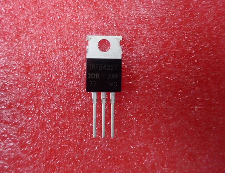
Details
BUY IRFB4227 IRFB4227PBF https://www.utsource.net/itm/p/12607319.html
| Parameter | Symbol | Test Conditions | Min | Typ | Max | Unit |
|---|---|---|---|---|---|---|
| Drain-Source On-Resistance | RDS(on) | VGS = 10V, ID = 39A (Tc = 25掳C) | 4.8 | - | 6.0 | m惟 |
| Gate Charge | QG | VDS = 10V, VGS = 10V | - | 71 | - | nC |
| Input Capacitance | Ciss | VDS = 10V | - | 1720 | - | pF |
| Output Capacitance | Coff | VDS = 10V | - | 42 | - | pF |
| Threshold Voltage | VGS(th) | ID = 250渭A | 2.0 | - | 4.0 | V |
| Continuous Drain Current | ID | TC = 25掳C | - | 39 | - | A |
| Power Dissipation | PD | TC = 25掳C | - | 170 | - | W |
| Junction Temperature | TJ | - | -55 | - | 175 | 掳C |
Instructions for IRFB4227 / IRFB4227PBF:
Handling and Storage:
- Store in a dry environment to prevent moisture damage.
- Handle with care to avoid damaging the leads and package.
Mounting:
- Ensure proper heat sinking if operating at high power levels.
- Follow manufacturer guidelines for PCB layout to minimize parasitic inductances.
Biasing and Drive:
- Use appropriate gate drive voltage (typically 10V) to ensure low RDS(on).
- Ensure gate drive circuitry can supply sufficient current to charge/discharge the gate capacitance quickly.
Operating Limits:
- Do not exceed maximum ratings for drain-source voltage, continuous drain current, or power dissipation.
- Operate within specified temperature ranges to ensure reliable performance.
Testing:
- Verify that all parameters meet specifications after installation.
- Regularly check for signs of overheating or abnormal operation.
Safety Considerations:
- Implement necessary safety measures to protect against electrical hazards.
- Use protective equipment when handling components at high voltages or currents.
View more about IRFB4227 IRFB4227PBF on main site