
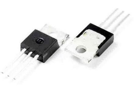
Details
BUY IRFB4410 https://www.utsource.net/itm/p/12611900.html
Below is the parameter table and instructions for the IRFB4410 MOSFET:
IRFB4410 Parameter Table
| Parameter | Symbol | Test Conditions | Min | Typ | Max | Unit |
|---|---|---|---|---|---|---|
| Drain-Source Voltage | VDSS | -55 | V | |||
| Gate-Source Voltage | VGSS | -20 | +20 | V | ||
| Continuous Drain Current | ID | TC = 25掳C | 38 | A | ||
| ID | TC = 75掳C | 29 | A | |||
| Pulse Drain Current | ID(p) | tp = 10 渭s, IGT = 4.5 V | 60 | A | ||
| Power Dissipation | Ptot | TC = 25掳C | 230 | W | ||
| Junction Temperature | TJ | 150 | 掳C | |||
| Storage Temperature Range | Tstg | -55 | 150 | 掳C | ||
| Thermal Resistance, Junction to Case | R胃JC | 0.5 | 掳C/W | |||
| Input Capacitance | Ciss | VDS = 25 V, f = 1 MHz | 1300 | pF | ||
| Output Capacitance | Coss | VDS = 25 V, f = 1 MHz | 260 | pF | ||
| Reverse Transfer Capacitance | Crss | VDS = 25 V, f = 1 MHz | 160 | pF | ||
| Gate Charge | Qg | VGS = 10 V, ID = 25 A | 100 | nC | ||
| Threshold Voltage | VGS(th) | ID = 250 渭A | 2.0 | 3.0 | 4.0 | V |
| On-State Resistance | RDS(on) | VGS = 10 V, ID = 25 A | 5.5 | m惟 | ||
| Turn-On Delay Time | td(on) | VGS = 10 V, ID = 25 A, VDS = 25 V | 18 | ns | ||
| Rise Time | tr | VGS = 10 V, ID = 25 A, VDS = 25 V | 28 | ns | ||
| Turn-Off Delay Time | td(off) | VGS = 10 V, ID = 25 A, VDS = 25 V | 20 | ns | ||
| Fall Time | tf | VGS = 10 V, ID = 25 A, VDS = 25 V | 25 | ns |
Instructions for Use
Handling and Storage:
- Store the device in a dry, cool place.
- Handle with care to avoid damage to the leads and the body of the device.
- Avoid exposing the device to high temperatures or humidity.
Mounting:
- Ensure proper heat sinking to manage the power dissipation and keep the junction temperature within safe limits.
- Use a thermal compound between the device and the heat sink for better thermal conductivity.
- Secure the device firmly to the heat sink to prevent mechanical stress.
Electrical Connections:
- Connect the gate (G), drain (D), and source (S) terminals correctly.
- Ensure that the gate-source voltage (VGS) does not exceed the maximum ratings.
- Use appropriate gate drive circuits to ensure reliable switching.
Operating Conditions:
- Do not exceed the maximum drain-source voltage (VDSS).
- Keep the continuous drain current (ID) within the specified limits for the given case temperature.
- Monitor the junction temperature (TJ) to ensure it does not exceed 150掳C.
Testing:
- Use a suitable test setup to measure the parameters such as on-state resistance (RDS(on)), gate charge (Qg), and switching times.
- Follow the test conditions specified in the parameter table for accurate measurements.
Safety:
- Always use appropriate safety measures when handling high-voltage and high-current circuits.
- Ensure that the device is properly isolated from other components during testing and operation.
By following these instructions, you can ensure the reliable and efficient operation of the IRFB4410 MOSFET.
(For reference only)View more about IRFB4410 on main site