
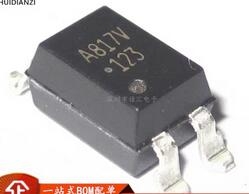
Details
BUY HCPL-817-300E https://www.utsource.net/itm/p/12611979.html
| Parameter | Symbol | Conditions | Min | Typ | Max | Unit |
|---|---|---|---|---|---|---|
| Forward Voltage | VF | IF = 20mA | 1.2 | 1.5 | V | |
| Reverse Voltage | VR | 5 | V | |||
| Forward Current | IF | Continuous | 50 | mA | ||
| Peak Pulse Current | IFP | t < 1ms | 150 | mA | ||
| Reverse Current | IR | VR = 5V | 100 | 渭A | ||
| CTR (Current Transfer Ratio) | CTR | IF = 5mA, VO = 5V | 100 | 300 | 600 | % |
| Output Collector-Emitter Voltage | VCEO | IC = 10mA | 70 | V | ||
| Output Collector Current | ICM | 50 | mA | |||
| Rise Time | tr | IF = 5mA, RL = 100惟 | 2 | 渭s | ||
| Fall Time | tf | IF = 5mA, RL = 100惟 | 2 | 渭s |
Instructions for HCPL-817-300E:
Power Supply and Connections:
- Ensure the forward voltage (VF) does not exceed 1.5V when operating at 20mA to prevent damage.
- Keep reverse voltage (VR) below 5V to avoid breakdown.
Current Handling:
- The device can handle a continuous forward current (IF) up to 50mA. For pulse applications, ensure peak pulse current (IFP) does not exceed 150mA for durations less than 1ms.
- Limit reverse current (IR) to no more than 100渭A at 5V reverse voltage.
CTR Consideration:
- The current transfer ratio (CTR) ranges from 100% to 600% under typical conditions (IF = 5mA, VO = 5V). Design circuits considering this range for reliable operation.
Output Specifications:
- Do not exceed 70V for collector-emitter voltage (VCEO) and limit output collector current (ICM) to 50mA.
Timing Parameters:
- Account for rise time (tr) and fall time (tf) of up to 2渭s in timing-sensitive applications.
Mounting and Environment:
- Ensure proper mounting to maintain thermal stability. Avoid exposing the device to excessive heat or moisture.
Safety Precautions:
- Always follow safety guidelines during handling and installation to prevent electrical shock or damage to the device.
View more about HCPL-817-300E on main site