
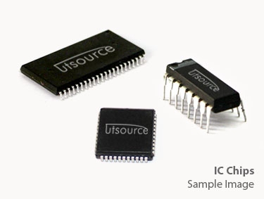
Details
BUY 74LVC1G14DBV https://www.utsource.net/itm/p/12611991.html
| Parameter | Symbol | Conditions | Min | Typ | Max | Unit |
|---|---|---|---|---|---|---|
| Input Voltage | V_I | 0 | 3.6 | V | ||
| Output Voltage | V_O | 0 | 3.6 | V | ||
| Supply Voltage | V_CC | 1.65 | 3.6 | V | ||
| Input Leakage Current | I_IL | V_I = 0V | -1 | 1 | 渭A | |
| Output Leakage Current | I_OL | V_O = 0V | -1 | 1 | 渭A | |
| Propagation Delay Time | t_PD | V_CC = 3.3V, T_A = 25掳C | 8 | ns | ||
| Power Dissipation | P_D | 47 | mW |
Instructions for Use:
Supply Voltage (V_CC):
- Ensure the supply voltage is within the range of 1.65V to 3.6V to prevent damage to the device.
Input Voltage (V_I):
- The input voltage should be between 0V and the supply voltage (V_CC). Exceeding these limits can cause malfunction or damage.
Output Voltage (V_O):
- The output voltage will be dependent on the logic state of the input and the supply voltage. It will typically be close to 0V for a low state and close to V_CC for a high state.
Propagation Delay (t_PD):
- For optimal performance, consider the propagation delay time when designing circuits. At 3.3V supply voltage, expect a typical delay of 8ns at room temperature.
Power Dissipation (P_D):
- Be mindful of power dissipation, especially in applications where multiple devices are used or in environments with limited heat dissipation capabilities. Do not exceed 47mW.
Handling:
- Handle with care to avoid electrostatic discharge (ESD) which can damage sensitive components. Use appropriate ESD protection measures during handling and installation.
Mounting:
- Ensure proper mounting orientation and connections as per the datasheet pin configuration to ensure reliable operation.
Environmental Considerations:
- Store and operate the device within recommended temperature and humidity ranges to maintain performance and reliability.
View more about 74LVC1G14DBV on main site