
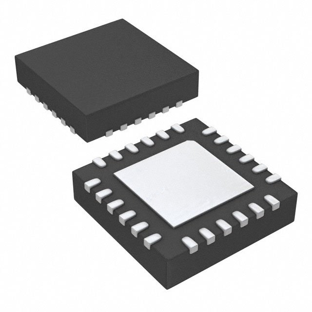
Details
BUY TPS560430XDBVR https://www.utsource.net/itm/p/12612279.html
Below is the parameter table and instructions for the TPS560430XDBVR, a 3A Synchronous Step-Down Converter from Texas Instruments.
Parameter Table
| Parameter | Symbol | Min | Typ | Max | Unit | Conditions |
|---|---|---|---|---|---|---|
| Input Voltage | VIN | 2.95 | - | 5.5 | V | |
| Output Voltage | VOUT | 0.8 | - | 3.6 | V | Adjustable via external resistors |
| Output Current | IOUT | - | 3 | - | A | Continuous output current |
| Switching Frequency | fSW | 500 | - | 2200 | kHz | Adjustable via external resistor |
| Efficiency (Typical) | η | - | 94 | - | % | At 3.3V input, 1.8V output, 1A load |
| Quiescent Current | IQ | - | 33 | - | μA | No load, VOUT = 3.3V |
| Shutdown Current | ISD | - | 0.1 | - | μA | VIN = 5V, SHDN = 0V |
| Soft-Start Time | tSS | - | 2.1 | - | ms | Typical, using 100nF capacitor |
| Thermal Shutdown Temperature | TSD | - | 160 | - | °C | |
| Operating Junction Temperature | TJ | -40 | - | 125 | °C |
Instructions
Power Supply Connection:
- Connect the input voltage (VIN) to the power supply within the range of 2.95V to 5.5V.
- Ensure that the input capacitor (CIN) is placed close to the VIN pin to minimize noise and improve stability.
Output Configuration:
- Set the output voltage (VOUT) by adjusting the external resistor divider network connected to the FB pin.
- The formula to calculate the output voltage is: [ V_ = V_ left(1 + fracright) ] where ( V_ = 0.8V ).
Switching Frequency Adjustment:
- Adjust the switching frequency (fSW) by connecting an external resistor (RT) between the RT/CLK pin and ground.
- The formula to calculate the switching frequency is: [ f_ = frac{1.2 times 10^6} ] where ( R_T ) is in ohms.
Soft-Start Configuration:
- Connect a capacitor (CSS) between the SS/TRK pin and ground to set the soft-start time.
- The typical soft-start time is 2.1ms with a 100nF capacitor.
Thermal Management:
- Ensure proper thermal management by placing the device on a PCB with adequate copper area for heat dissipation.
- Avoid operating the device at temperatures exceeding 125°C to prevent thermal shutdown.
Enable/Shutdown Control:
- Apply a high logic level (≥1.2V) to the EN pin to enable the converter.
- Apply a low logic level (≤0.4V) to the EN pin to shut down the converter, reducing the quiescent current to 0.1μA.
Output Inductor Selection:
- Choose an inductor with a value that provides stable operation and meets the ripple current requirements.
- Refer to the datasheet for recommended inductor values based on the desired output current and switching frequency.
Output Capacitor Selection:
- Use a low ESR ceramic capacitor for the output to ensure good transient response and stability.
- The output capacitor should have a capacitance and ESR that meet the design requirements for the specific application.
By following these instructions, you can effectively configure and use the TPS560430XDBVR in your design.
(For reference only)View more about TPS560430XDBVR on main site