
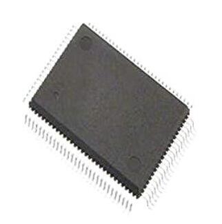
Details
BUY TM4C129ENCPDTI3R https://www.utsource.net/itm/p/12612290.html
| Parameter | Description | Value | Unit |
|---|---|---|---|
| Part Number | Full Part Number | TM4C129ENCPDTI3R | - |
| Package | Package Type | TQFP-100 | - |
| Operating Voltage (Vcc) | Supply Voltage Range | 3.0 to 3.6 | V |
| Operating Temperature | Industrial Temperature Range | -40 to 85 | 掳C |
| Flash Memory | Program Memory Size | 1024 | KB |
| SRAM | Data Memory Size | 256 | KB |
| Clock Speed | Maximum Clock Frequency | 120 | MHz |
| Analog-to-Digital Converter (ADC) | Number of ADC Channels | 12 | - |
| Digital-to-Analog Converter (DAC) | Number of DAC Channels | 2 | - |
| General-Purpose I/O (GPIO) | Number of GPIO Pins | 72 | - |
| Communication Interfaces | Supported Protocols | UART, SPI, I2C, USB, CAN, Ethernet | - |
| Timers | Number of Timers | 12 | - |
| Watchdog Timer | Watchdog Timer | Yes | - |
| DMA Channels | Number of DMA Channels | 16 | - |
| Interrupts | Number of Interrupt Lines | 80 | - |
| Power Management | Low Power Modes | Sleep, Deep Sleep, Shutdown | - |
| JTAG | JTAG Support | Yes | - |
| Package Dimensions | Width x Length x Height | 14 x 14 x 1.4 | mm |
Instructions for Use:
Power Supply:
- Ensure the supply voltage (Vcc) is within the specified range of 3.0 to 3.6V.
- Connect the power supply to the appropriate Vcc and GND pins.
Clock Configuration:
- Configure the system clock to run at the desired frequency up to 120 MHz.
- Use the internal or external oscillators as needed.
Memory Initialization:
- Initialize the flash memory and SRAM before running any application code.
- Use the provided startup code or initialize manually.
GPIO Configuration:
- Configure the GPIO pins for input, output, or alternative functions as required.
- Set pull-up or pull-down resistors if necessary.
Peripheral Configuration:
- Initialize the communication interfaces (UART, SPI, I2C, USB, CAN, Ethernet) according to the application requirements.
- Configure the ADC and DAC channels for analog signal processing.
Timer and Interrupt Setup:
- Set up the timers for periodic events or delays.
- Configure interrupts to handle specific events or conditions.
Power Management:
- Implement low power modes (Sleep, Deep Sleep, Shutdown) to reduce power consumption when not actively processing data.
JTAG Debugging:
- Connect the JTAG interface for debugging and programming the device.
- Use a compatible debugger and software development environment.
Software Development:
- Use a supported IDE (e.g., Keil, IAR, Code Composer Studio) for writing and compiling code.
- Refer to the datasheet and user manual for detailed information on registers and configuration settings.
Testing and Validation:
- Test the device in a controlled environment to ensure it meets the application requirements.
- Validate the functionality of all configured peripherals and interfaces.
For more detailed information, refer to the TM4C129ENCPDTI3R datasheet and user manual.
(For reference only)View more about TM4C129ENCPDTI3R on main site