
Details
BUY LAN9252I/PT https://www.utsource.net/itm/p/12612291.html
| Parameter | Description | Value |
|---|---|---|
| Device Type | Ethernet Controller with USB 2.0 Host and 10/100 PHY | - |
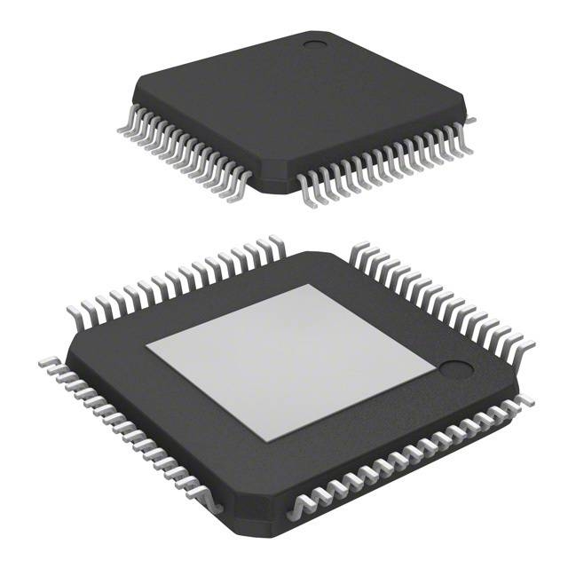
| Package | TQFP-64 (10x10mm) | - |
| Operating Voltage (Vcc) | Supply Voltage for Digital Core | 3.3V ± 5% |
| Operating Voltage (Vio) | I/O Supply Voltage | 1.8V to 3.3V |
| Operating Temperature Range | Industrial Temperature Range | -40°C to +85°C |
| Ethernet Interface | IEEE 802.3 10/100BASE-TX | - |
| USB Interface | USB 2.0 High-Speed (480 Mbps) Host | - |
| GPIO | General Purpose Input/Output Pins | 24 |
| SPI Interface | Serial Peripheral Interface | Up to 50 MHz |
| I2C Interface | Inter-Integrated Circuit | Up to 400 kHz |
| UART Interface | Universal Asynchronous Receiver/Transmitter | 1 x UART |
| WAKE# Pin | Wake-on-LAN Pin | - |
| MDIO Interface | Management Data Input/Output | - |
| Power Consumption | Typical Power Consumption (Active) | 200 mW |
| Standby Power Consumption | Typical Power Consumption (Standby) | 10 mW |
| ESD Protection | Electrostatic Discharge Protection | ±2 kV HBM, ±1 kV CDM |
| RoHS Compliance | Restriction of Hazardous Substances | Yes |
Instructions for Use
Power Supply Configuration:
- Connect the Vcc pin to a 3.3V power supply.
- Connect the Vio pins to a 1.8V to 3.3V power supply, depending on your application requirements.
Reset and Initialization:
- Apply a reset signal to the RESET# pin to initialize the device.
- Ensure the reset signal is held low for at least 100 μs before releasing it.
Ethernet Connection:
- Connect the RJ45 connector to the Ethernet PHY using the appropriate pins (TX+/TX-, RX+/RX-).
- Configure the MDIO interface to manage the PHY settings if needed.
USB Host Configuration:
- Connect the USB D+ and D- lines to the USB host port.
- Configure the USB controller through the SPI or I2C interface as required.
GPIO Configuration:
- Configure the GPIO pins for input or output based on your application needs.
- Set the direction and state of each GPIO pin via the SPI or I2C interface.
SPI/I2C/UART Interfaces:
- Connect the SPI, I2C, or UART interfaces to your microcontroller or processor.
- Configure the communication parameters (e.g., clock speed, data format) as specified in the datasheet.
Wake-on-LAN:
- Connect the WAKE# pin to a wake-up circuit or microcontroller.
- Configure the WAKE# pin to generate a wake-up signal when network activity is detected.
Firmware and Software:
- Load the appropriate firmware onto the device to enable desired functionalities.
- Use the provided software libraries and drivers to facilitate communication and control.
Thermal Considerations:
- Ensure adequate heat dissipation by providing a heatsink or thermal pad if necessary.
- Monitor the temperature of the device to avoid overheating.
ESD Protection:
- Handle the device with care to avoid electrostatic discharge.
- Use ESD-protected workstations and tools during handling and assembly.
For detailed configuration and programming instructions, refer to the LAN9252I/PT datasheet and application notes provided by the manufacturer.
(For reference only)View more about LAN9252I/PT on main site