
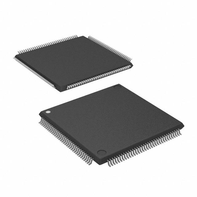
Details
BUY ATSAME70Q21A-AN https://www.utsource.net/itm/p/12612295.html
| Parameter | Description | Value |
|---|---|---|
| Device Type | Microcontroller | ATSAME70Q21A-AN |
| Package | LFBGA (144-pin) | 144 |
| Operating Voltage | Supply Voltage Range | 1.62V to 3.63V |
| Clock Speed | Maximum CPU Frequency | 300 MHz |
| Flash Memory | Program Memory Size | 2 MB |
| RAM | Data Memory Size | 384 KB |
| Temperature Range | Operating Temperature Range | -40掳C to +85掳C |
| I/O Pins | Number of I/O Pins | 109 |
| Analog-to-Digital Converter (ADC) | Number of ADC Channels and Resolution | 12-bit, 16 channels |
| Digital-to-Analog Converter (DAC) | Number of DAC Channels and Resolution | 12-bit, 2 channels |
| Timers | Number of Timers and Types | 5 x 32-bit, 2 x 16-bit |
| Serial Communication Interfaces (SCI) | Number of SCI Interfaces | 4 |
| SPI | Number of SPI Interfaces | 3 |
| I2C | Number of I2C Interfaces | 2 |
| USB | USB Interface | USB 2.0 Full Speed |
| CAN | CAN Interface | 2 x CAN 2.0B |
| Watchdog Timer | Watchdog Timer | Yes |
| Low Power Modes | Low Power Modes | Sleep, Deep Sleep, Standby |
| Interrupts | Number of Interrupt Vectors | 128 |
| Capacitance Touch Sensing | Capacitance Touch Sensing Channels | 24 |
| Package Dimensions | Package Dimensions (LxWxH) | 10 mm x 10 mm x 1.0 mm |
| Weight | Weight | 0.3 g |
Instructions for Use
Power Supply:
- Ensure the supply voltage is within the range of 1.62V to 3.63V.
- Connect the VDD and VSS pins to the power source and ground, respectively.
Clock Configuration:
- The microcontroller supports an internal RC oscillator and external crystal oscillators. Configure the clock source using the system control registers.
Flash and RAM Management:
- The device has 2 MB of flash memory and 384 KB of RAM. Use the provided libraries or direct register manipulation to manage memory.
Peripheral Initialization:
- Initialize the required peripherals (ADC, DAC, timers, UART, SPI, I2C, USB, CAN) by configuring their respective control registers.
Interrupt Handling:
- Set up interrupt vectors and enable interrupts for the desired peripherals. Handle interrupts in the appropriate interrupt service routines (ISRs).
Low Power Modes:
- Enter low power modes (Sleep, Deep Sleep, Standby) by configuring the power management registers. Ensure that wake-up sources are properly set up.
Capacitive Touch Sensing:
- Use the capacitive touch sensing channels to detect touch events on capacitive sensors. Configure the touch sensing controller (TSC) and process the sensor data.
Programming and Debugging:
- Use a JTAG or SWD interface for programming and debugging. Connect to the microcontroller using a debugger and programming tool compatible with the ATSAME70Q21A-AN.
Software Development:
- Utilize development tools and IDEs such as Atmel Studio, ARM Keil, or IAR Embedded Workbench to write and compile your code.
- Refer to the datasheet and reference manuals for detailed information on register configurations and peripheral usage.
Thermal Considerations:
- Ensure proper thermal management by providing adequate heat dissipation, especially when operating at high frequencies or under heavy loads.
Electrostatic Discharge (ESD) Protection:
- Handle the device with ESD precautions to avoid damage. Use grounded wrist straps and ESD-safe workstations.
Storage and Handling:
- Store the device in a dry and cool environment. Follow recommended storage conditions to ensure long-term reliability.
View more about ATSAME70Q21A-AN on main site