
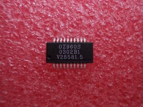
Details
BUY OZ960S https://www.utsource.net/itm/p/12612339.html
| Parameter | Description | Value |
|---|---|---|
| Device Type | High Efficiency Step-Up DC-DC Converter | - |
| Input Voltage (VIN) | Operating Input Voltage Range | 2.7V to 15V |
| Output Voltage (VOUT) | Adjustable Output Voltage | 3.3V to 15V |
| Output Current (IOUT) | Maximum Continuous Output Current | 3A |
| Switching Frequency | Fixed Switching Frequency | 600kHz |
| Quiescent Current | Current Consumption in Standby Mode | 10渭A |
| Efficiency | Typical Efficiency at Full Load | Up to 95% |
| Protection Features | Overcurrent Protection, Overvoltage Protection, Thermal Shutdown | - |
| Package Type | SOT-23-6 | - |
| Operating Temperature | Ambient Operating Temperature Range | -40掳C to +85掳C |
Instructions for Use
Power Supply Connection:
- Connect the input power supply to the VIN and GND pins.
- Ensure the input voltage is within the specified range (2.7V to 15V).
Output Configuration:
- Adjust the output voltage using an external resistor divider network connected to the FB (Feedback) pin.
- The output voltage can be calculated using the formula: VOUT = 1.23V * (1 + R1/R2), where R1 and R2 are the resistors in the feedback network.
Capacitor Selection:
- Use a low ESR ceramic capacitor (10渭F to 100渭F) on the input side to ensure stable operation.
- Use a low ESR ceramic capacitor (10渭F to 100渭F) on the output side to filter the output voltage.
Inductor Selection:
- Choose an inductor with a saturation current rating higher than the maximum output current (3A).
- A typical inductor value is 4.7渭H to 10渭H.
Thermal Management:
- Ensure adequate heat dissipation by providing a good thermal path to the PCB or using a heatsink if necessary.
- Monitor the device temperature to avoid exceeding the maximum operating temperature.
Protection Circuits:
- The OZ960S includes built-in overcurrent, overvoltage, and thermal protection features.
- In case of a fault, the device will automatically shut down and restart after the fault condition is cleared.
Layout Considerations:
- Keep the input and output capacitors as close as possible to the IC to minimize parasitic inductance.
- Use wide traces for power paths to reduce resistance and improve efficiency.
Testing:
- After assembly, test the circuit under various load conditions to ensure it meets the desired performance specifications.
- Verify the output voltage stability and efficiency.
Storage:
- Store the device in a dry, cool place to prevent moisture damage.
- Handle with care to avoid static discharge, which can damage the sensitive components.
View more about OZ960S on main site