
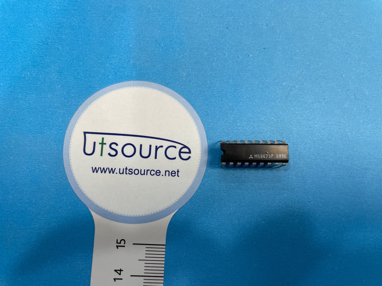
Details
BUY M58473P https://www.utsource.net/itm/p/12614068.html
| Parameter | Symbol | Conditions | Min | Typ | Max | Unit |
|---|---|---|---|---|---|---|
| Supply Voltage | Vcc | Operating | 2.7 | - | 5.5 | V |
| Output Current | Iout | Continuous | - | 100 | 200 | mA |
| Quiescent Current | Iq | Vcc = 5V, No Load | - | 1.5 | 3.0 | mA |
| Dropout Voltage | Vdo | Iout = 100mA, Vcc = 5V | - | 0.6 | 1.2 | V |
| Line Regulation | ΔVL/ΔVI | Vcc = 3V to 5.5V, Iout = 0 to 100mA | - | 0.01 | - | %/V |
| Load Regulation | ΔVL/ΔIout | Vcc = 5V, Iout = 0 to 100mA | - | 0.01 | - | %/mA |
| Thermal Shutdown Temperature | TSD | - | - | 150 | 170 | °C |
| Storage Temperature Range | Tstg | - | -65 | - | 150 | °C |
Instructions for Using M58473P:
Supply Voltage (Vcc):
- Ensure the supply voltage is within the range of 2.7V to 5.5V.
- Avoid exceeding the maximum voltage to prevent damage to the device.
Output Current (Iout):
- The device can provide a continuous output current of up to 200mA.
- For optimal performance, keep the output current below 100mA.
Quiescent Current (Iq):
- The quiescent current is typically 1.5mA at 5V with no load.
- This value helps in power budgeting for low-power applications.
Dropout Voltage (Vdo):
- The dropout voltage is the minimum difference between the input and output voltages required to maintain regulation.
- At 100mA output current and 5V input, the typical dropout voltage is 0.6V.
Line Regulation:
- The line regulation is the change in output voltage due to changes in input voltage.
- It is typically 0.01% per volt, indicating good stability over varying input conditions.
Load Regulation:
- The load regulation is the change in output voltage due to changes in output current.
- It is typically 0.01% per milliamp, indicating good stability over varying load conditions.
Thermal Shutdown:
- The device will automatically shut down if the junction temperature exceeds 150°C to 170°C to prevent thermal damage.
- Ensure adequate heat dissipation or cooling mechanisms are in place.
Storage Temperature:
- Store the device in an environment where the temperature ranges from -65°C to 150°C to ensure long-term reliability.
Mounting and Handling:
- Handle the device with care to avoid static discharge and physical damage.
- Follow recommended soldering profiles and mounting guidelines to ensure proper installation.
Application Notes:
- Refer to the datasheet for detailed application notes and circuit diagrams.
- Consider using bypass capacitors on the input and output to improve stability and reduce noise.
View more about M58473P on main site