
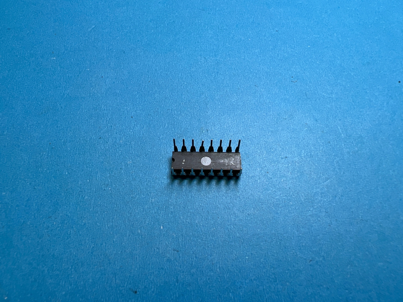
Details
BUY HEF4517BP https://www.utsource.net/itm/p/12617534.html
| Parameter | Symbol | Conditions | Min | Typ | Max | Unit |
|---|---|---|---|---|---|---|
| Supply Voltage | VCC | Operating | 3 | - | 18 | V |
| Input Voltage (High) | VIH | - | 2 | - | VCC | V |
| Input Voltage (Low) | VIL | - | 0 | - | 0.8 | V |
| Output Voltage (High) | VOH | IO = -1 mA | - | VCC - 0.5 | VCC - 0.1 | V |
| Output Voltage (Low) | VOL | IO = 1 mA | 0 | 0.1 | 0.5 | V |
| Input Current (High) | IIH | - | - | 1 | 20 | 渭A |
| Input Current (Low) | IIL | - | -1 | - | -20 | 渭A |
| Output Current (Source) | IOH | VO = VCC - 1.5V | - | 4 | 6 | mA |
| Output Current (Sink) | IOL | VO = 0.4V | - | 10 | 16 | mA |
| Propagation Delay Time | tpd | VCC = 10V, fL = 1 kHz | - | 50 | 100 | ns |
| Power Dissipation | PD | - | - | - | 100 | mW |
Instructions for Use:
Power Supply:
- Ensure the supply voltage (VCC) is within the range of 3V to 18V.
- Connect VCC to the positive supply and GND to the ground.
Input Signals:
- For a high input signal, ensure the voltage (VIH) is at least 2V but can go up to VCC.
- For a low input signal, ensure the voltage (VIL) is between 0V and 0.8V.
- The input current (IIH and IIL) should be within the specified limits to avoid damage.
Output Signals:
- When the output is high, the voltage (VOH) will be between VCC - 0.5V and VCC - 0.1V.
- When the output is low, the voltage (VOL) will be between 0V and 0.5V.
- The output current (IOH and IOL) should be within the specified limits to avoid damage.
Propagation Delay:
- The propagation delay time (tpd) is the time it takes for the output to change state after the input changes. It is typically between 50ns and 100ns at VCC = 10V.
Power Dissipation:
- The maximum power dissipation (PD) is 100mW. Ensure that the device does not exceed this limit to prevent overheating and potential failure.
Handling:
- Handle the HEF4517BP with care to avoid static discharge, which can damage the device.
- Store the device in a dry, cool place away from direct sunlight.
Mounting:
- Ensure proper mounting on the PCB to maintain good electrical connections and thermal dissipation.
- Follow the recommended soldering profile to avoid thermal stress during assembly.
View more about HEF4517BP on main site