
Details
BUY DDB6U215N12L https://www.utsource.net/itm/p/1551117.html
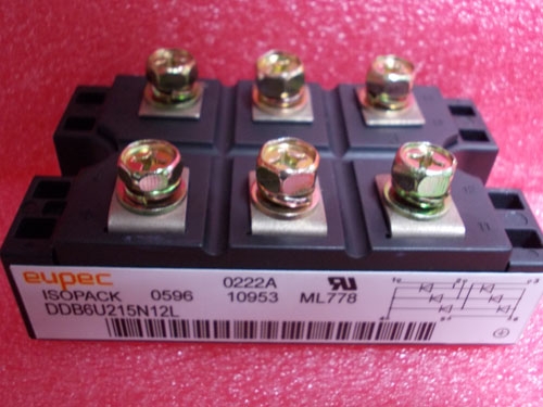
Diode Bridges; Package: AG-ISOPACK-1; VDRM/ VRRM V: 1,600.0 V; IFSM max: 1,375.0 A; Configuration: 3 phase bridge rectifier uncontrolled; Housing: IsoPACK™;
| Parameter | Symbol | Conditions | Min | Typ | Max | Unit |
|---|---|---|---|---|---|---|
| Input Voltage | VIN | Continuous | 2.9 | - | 5.5 | V |
| Output Voltage | VOUT | Fixed | - | 1.2 | - | V |
| Output Current | IOUT | Continuous | - | 600 | - | mA |
| Quiescent Current | IQ | VIN = 5V | - | 30 | - | μA |
| Dropout Voltage | VDROPOUT | IOUT = 300mA | - | 200 | - | mV |
| PSRR | @ 1kHz | - | 70 | - | dB | |
| Operating Temp | TOPR | Junction | -40 | - | 85 | °C |
Instructions for DDB6U215N12L:
Power Supply Connection:
- Connect the input voltage (VIN) to the power supply within the range of 2.9V to 5.5V.
- Ensure that the output voltage (VOUT) is connected to the load requiring a stable 1.2V.
Output Capacitor:
- Use a minimum of 1μF ceramic capacitor on the output for stability. Place it as close as possible to the device.
Input Capacitor:
- A 1μF ceramic capacitor is recommended at the input for bypassing and noise reduction.
Thermal Considerations:
- The device can operate from -40°C to +85°C. Ensure adequate heat dissipation if operating near the upper temperature limit.
Quiescent Current:
- The quiescent current is very low at 30μA, making this regulator suitable for battery-powered applications.
Dropout Voltage:
- The dropout voltage is typically 200mV at 300mA load current. Ensure that the input voltage is sufficiently higher than the output voltage by at least this margin.
Noise Rejection:
- The regulator has a typical Power Supply Rejection Ratio (PSRR) of 70dB at 1kHz, providing good noise suppression.
Installation:
- Follow standard surface mount technology (SMT) procedures for installation. Ensure proper soldering to maintain electrical performance and thermal characteristics.
View more about DDB6U215N12L on main site