
Details
BUY STM32F3348-DISCO https://www.utsource.net/itm/p/7282542.html
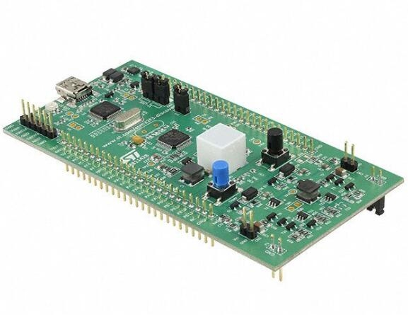
Discovery Kit for STM32F334R8 Microcontroller The 32F3348DISCOVERY Discovery kit helps you to discover the digital power features of the STM32F334 microcontrollers. The board assists the user in developing applications with everything required to start quickly. Features include is an ST-LINK/V2-1 embedded debug tool interface, high brightness LED dimming with buck converter, buck/boost converter, LEDs and push buttons. STM32F334C8T6 microcontroller featuring 64 KB of Flash memory, 12 KB RAM in an LQFP48 package On-board ST-LINK/V2-1 debugger/programmer with selection mode switch and SWD connector ARM mbed-enabled (mbed.org) Virtual Com port, Mass storage, and Debug port interfaces supported on USB USB bus power supply or from an external 5 V supply High brightness LED dimming with buck converter Buck / Boost converter Six LEDs: Power on, USB communication, and four different colour user LEDs USER and RESET Push Buttons Extension connection header for LQFP48 Inputs/Outputs
| Parameter | Description |
|---|---|
| Product Name | STM32F3348-DISCO Discovery Kit |
| Microcontroller | STM32F334C8T6 |
| Core | ARM? Cortex?-M4 32-bit core |
| Frequency | Up to 72 MHz |
| Voltage (VDD) | 1.8 V to 3.6 V |
| Flash Memory | 64 KB |
| RAM | 16 KB |
| Operating Temperature | -40 °C to +85 °C |
| Analog Features | ADC, DAC, Comparators |
| Digital Communication | UART, SPI, I2C, CAN |
| USB Interface | USB 2.0 Full Speed Device |
| Power Supply | USB or external source |
| Expansion Headers | Arduino Uno V3 and Morpho headers |
| Debug Interface | ST-LINK/V2-1 on-board debugger/programmer |
| Clock Sources | Internal: HSI 8 MHz RC oscillator, LSI ~40 kHz RC oscillator |
| External: HSE 4 to 26 MHz crystal oscillator, LSE 32.768 kHz crystal | |
| Timer | Basic, general-purpose, advanced-control PWM, low-power |
| DMA Channels | 12 channels |
| Package | LQFP64 |
Instructions for Use:
Setup and Installation
- Connect the STM32F3348-DISCO board to your computer using a micro USB cable.
- Install the necessary drivers from the ST website if not automatically recognized by your system.
Programming Environment
- Use STM32CubeMX to configure the MCU pinout and clock settings.
- Generate initialization code and integrate it into your project using an IDE like TrueSTUDIO or Keil MDK.
Debugging
- Utilize the on-board ST-LINK/V2-1 for debugging via SWD interface.
- Set breakpoints, step through code, and inspect variables directly in your IDE.
Powering the Board
- Power can be supplied via the USB connection or through an external power supply connected to the VIN pin (5V).
Using Expansion Headers
- Connect peripherals using the Arduino Uno V3 or Morpho headers as needed for your application.
Testing Analog and Digital Interfaces
- Configure ADC, DAC, and digital communication interfaces (UART, SPI, I2C, CAN) according to your project requirements.
- Test each interface with simple read/write operations to ensure correct functionality.
Referencing Documentation
- Always refer to the official STM32F3348-DISCO user manual and datasheet for detailed specifications and programming guidelines.
View more about STM32F3348-DISCO on main site