
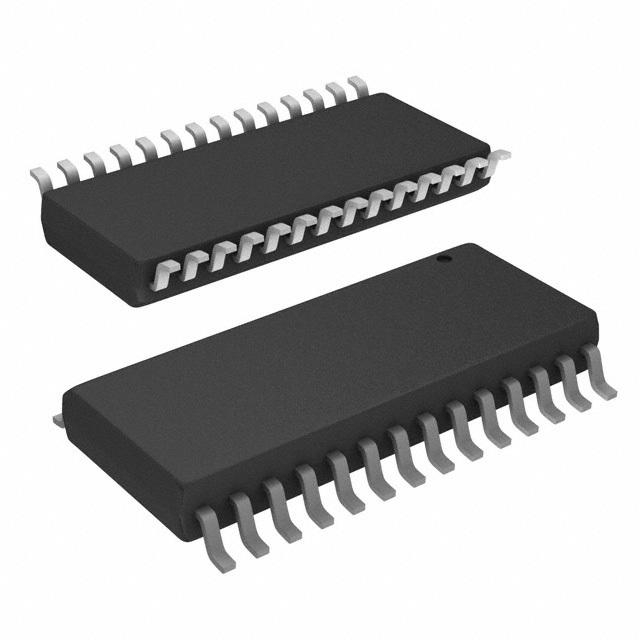
Details
BUY PIC16F1513-E/SO https://www.utsource.net/itm/p/7441419.html
PIC PIC? XLP? 16F Microcontroller IC 8-Bit 20MHz 7KB (4K x 14) FLASH 28-SOIC
| Parameter | Description | PIC16F1513-E/SO Specifications |
|---|---|---|
| Package Type | Package format | SOIC (Small Outline Integrated Circuit) |
| Pin Count | Number of pins | 14 |
| Operating Voltage | Supply voltage range | 2.0V to 5.5V |
| Operating Temperature | Temperature range for operation | -40°C to +85°C |
| Program Memory Size | Size of program memory | 7K x 14 |
| Data RAM | Size of data memory | 256B |
| EEPROM | Size of EEPROM memory | 256B |
| Clock Speed | Maximum clock frequency | 32 MHz |
| I/O Pins | Number of I/O pins | 11 |
| Analog-to-Digital Channels (ADC) | Number of ADC channels | 10-bit, up to 8 channels |
| Timers | Number and type of timers | 3 x 8/16-bit Timers |
| Comparator Modules | Number of comparator modules | 2 |
| USART Module | Universal Synchronous Asynchronous Receiver Transmitter | 1 |
| SPI/I2C Module | Serial Peripheral Interface / Inter-Integrated Circuit | 1 |
| Brown-out Reset (BOR) | Feature to reset the device when supply voltage drops below a threshold | Yes |
| Watchdog Timer (WDT) | Timer to reset the device if it hangs | Yes |
| Low-Voltage Programming (LVP) | Capability to be programmed at low voltages | Yes |
Instructions for Use:
- Power Supply: Ensure the operating voltage is within the specified range (2.0V to 5.5V). Connect VDD to the positive supply and VSS to ground.
- Programming: The device supports Low-Voltage Programming (LVP). Use a suitable programmer compatible with the PIC16F1513-E/SO.
- Clock Configuration: Configure the internal oscillator or connect an external crystal/clock source based on your application needs.
- Reset Pin: Connect a pull-up resistor to the MCLR pin if using external reset functionality.
- Analog Inputs: For ADC channels, ensure analog inputs are connected to appropriate pins and configure the ADC module via software.
- Digital I/O: Configure digital I/O pins as input or output in your code. Use built-in pull-ups where necessary.
- Peripheral Modules: Initialize and configure peripherals like USART, SPI/I2C, and comparators according to your application requirements.
- Power-On Reset (POR): Ensure proper power sequencing to utilize POR effectively.
- Brown-Out Reset (BOR): Adjust BOR settings in the configuration bits to protect against low-voltage conditions.
- Watchdog Timer (WDT): Enable and set WDT intervals to prevent software lockups.
For detailed programming instructions and specific register configurations, refer to the official Microchip datasheet for the PIC16F1513-E/SO.
(For reference only)View more about PIC16F1513-E/SO on main site